how to draw a 3d retaing wall
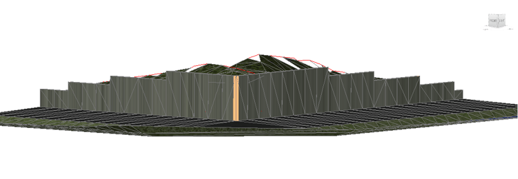
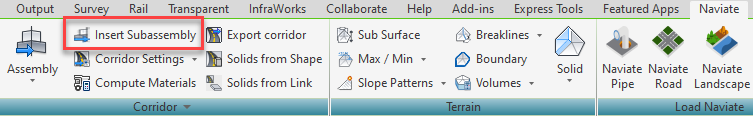
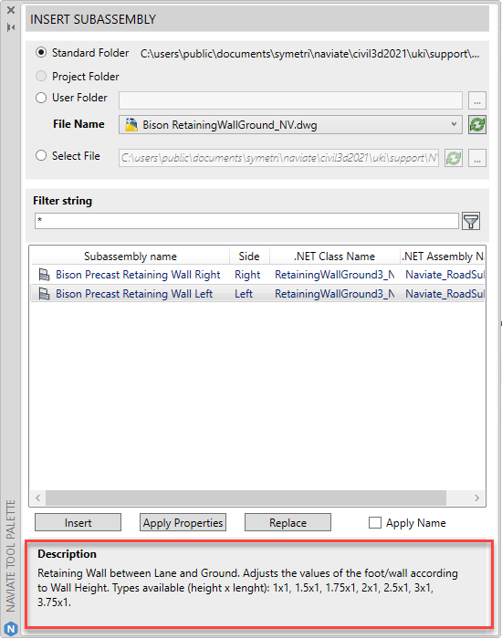
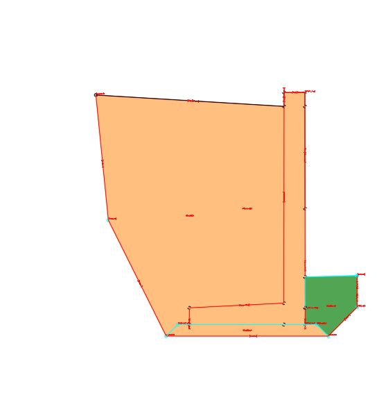
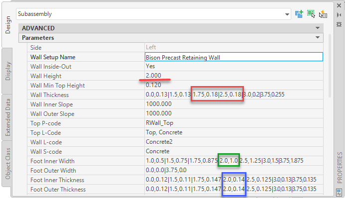
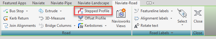
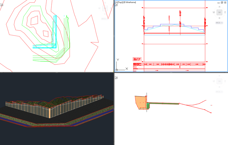
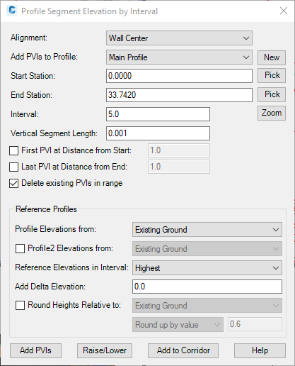
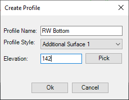
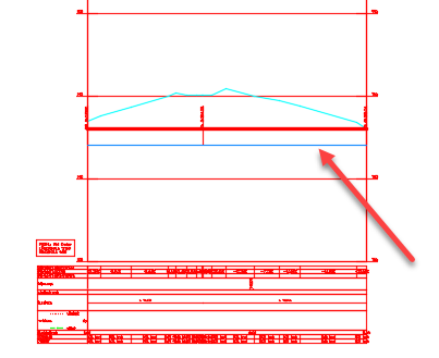
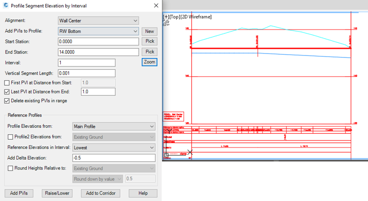
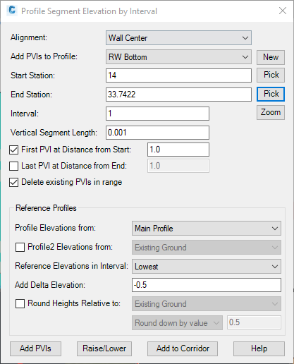
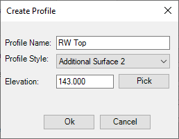
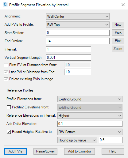
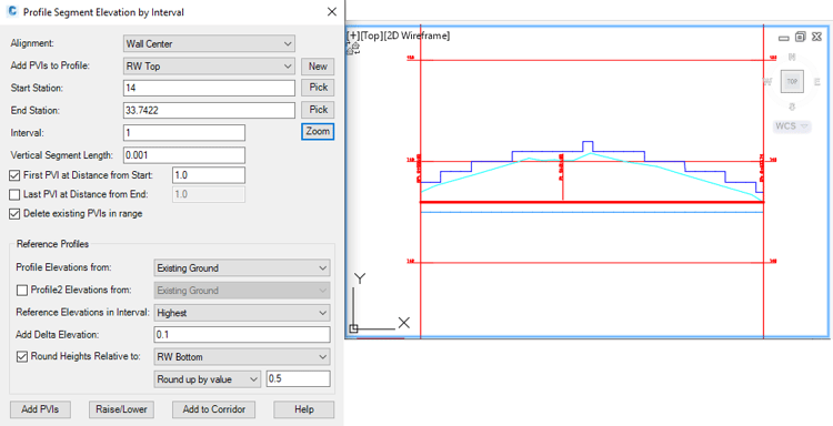
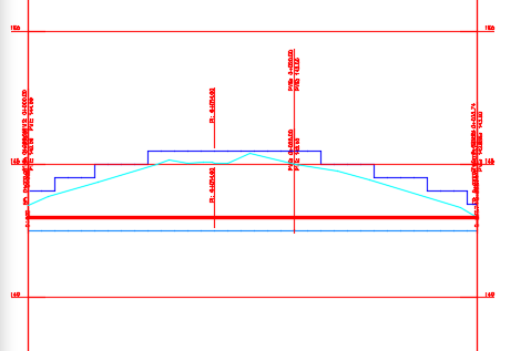
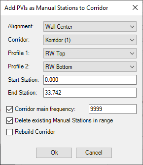
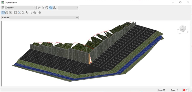
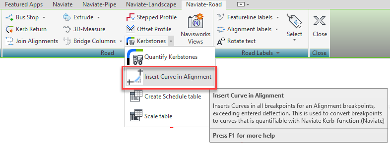
This post is office 1/3 in a series on retaining wall. Naviate take commands that tin can help you pattern a retaining wall after a manufacturer's standard sizes. There are some steps to get to the last result, summarised information technology volition expect something like this; Let´s go through the steps! To import a retaining wall subassembly, go to the Naviate-tab in the Ribbon and in the Corridor-Panel find Insert Subassembly. You'll find the retaining wall subassemblies in the standard folder, set up for use both against lanes or against ground, likewise as on the left or right side. Select 1 of the retaining walls and you will meet a description field at the bottom of the dialogue, displaying data about the retaining wall, such as bachelor dimensions from the retailer. When the Retaining Wall is inserted to the drawing, you can view and change the parameters in Properties or Subassembly Properties as per usual. Equally written in the description in the Import Subassembly dialogue, the thickness of the foot, the foot length and the thickness of the wall will vary according to the wall height. (If you like to dig in to how the subassembly works, keep reading. If you just want to get the elevation and bottom height of the retaining wall correct, please go to step ii.) The Wall height in this example is 2,0 m (see the underlined text in cerise below). The Wall Thickness depends on the peak. The numbers in the cherry-red rectangle means that if the wall is 1,75 m high - the wall thickness is 0,18 one thousand. The format is wall height comma sign thickness of the wall for that height. The vertical line separates the heights. If the wall is ii.5 1000 meridian, the thickness is still 0,xviii m. Betwixt the heights, the thickness is interpolated. Therefore, the thickness is 0,18 meters for a 2,0 yard wall height. Moving on to the Foot Inner Width that works the same, the light-green rectangle. For a 2,0 thousand wall summit, the inner width is 1,0 one thousand. Foot Inner/Outer Thickness is 0,14 m for a 2,0 k wall pinnacle, as seen in the bluish triangle. Try to change the height and see what happens with the foot and thickness of the wall. To fix the top for the retaining wall top or/and lesser, apply the Naviate command Stepped Profile. The drawing in the following case contains an alignment, profile and a corridor made with an assembly including a retaining wall subassembly. Side annotation: Civil 3D has a problem rendering the 3D view in the third quadrant. How this is solved is shown in Stride four. To get the retaining wall to represent the length and top of the different retaining wall elements the retailer offers, run the command Stepped Profile. Alignment: Start with selecting the alignment the profile is connected to. Add PVIs to Profile: Select an already existing profile or klick New to create a new 1. In this example we will do a stepped profile both for the acme and bottom of the retaining wall. Start with creating a profile for the bottom. Write a name and select a way and an acme. Klick OK and the profile, in this case the retaining wall meridian is added to the existing profile view. Back to the Stepped Profile dialogue. To set the retaining wall element (length and heights) for the commencement role, select showtime and finish station. Start station volition exist 0 and End station in this case will be the corner. Why is that? Well, the corner elements from the retailer often comes in a piece of 1 m on each side of the corner. Hence why yous should in that case check the Concluding PVI at Distance from Terminate. Interval will be 1 considering the retaining wall elements comes with lengths of one meter. In this example the Bison Retaining wall is used, and in the Naviate support files there is a CSV file with information about the elements from Bison. The bottom profile will be 0.5 meters below the main profile. When you are done with the settings from the start to the corner, click Add PVIs and the first office of the contour is stepped in the profile view. Next step volition exist the residual of the alignment for the bottom, from start station 14 to the stop station. From the corner, station fourteen, nosotros want that i-meter element again, so brand sure to check the First PVI at distance from beginning. The settings nether Reference Profiles will remain. Klick Add PVIs and the rest of the profile is at present stepped. When finished with the stepped profile for RW Lesser, next step is to create the top. Start with calculation PVIs from station 0 to the corner, station xiv. Don't forget to bank check the PVI distance from cease. Reference profile will be the existing ground and the pinnacle contour will be 0.i meter above the existing basis. If you exit the dialogue and measure the distance from bottom to top, it will most likely be an uneven number. The standard summit from the retailer is i-three meters in 0.5 m interval, therefore bank check the Round heights Relative to RW Bottom, and Round up by value 0.5 meter. Click Add PVIs. Fill in the settings for the rest of the profile and klick Add PVIs again. If you want to change a tiptop for an element, klick Enhance/Lower button and you can change one pace at a fourth dimension. Hither I have inverse the highest segment to friction match the lower i next to information technology. The last pace for the command is to click the Add to Corridor button. A new dialogue pops up where you lot will select the settings for the corridor stations. To get the corridor to be congenital with the correct stations for the stepped profile, fill in the dialogue for the retaining wall top and/or bottom every bit Contour 1 and 2. Also select the first and end station for the retaining wall and the rest of the settings and click OK. In the Corridor Properties, gear up the target for the Top Profile to RW Top for the Retaining Wall subassembly (and/ or bottom of class). Rebuild the corridor. Every bit the stations for the stepped profile for the retaining wall are added to the corridor, you will at present see the dissimilar retaining wall elements in the 3D-view. It notwithstanding looks like there is a gap in the corner, merely it is only Ceremonious 3D having problem rendering the 3D view. The rendering problem could be solved via inserting a small radius in the corner. Preferably with the Insert Bend in Alignment command. Insert a small curve in the corner and rebuild the corridor. The 3D view now looks good. Note that the stations in the alignment also changes as the curve is inserted. Depending on what's important in your situation, the stepped profile control should be run once again on the updated alignment to become it all correct (or of form the curve could be inserted before the stepped profile command was run). Instead of picking the corner every bit the End Station, pick the first point on the bend. When defining the elevations from the corner to the finish, option Offset Station equally the end of the curve.
And in the third post y'all tin read about using match properties to apply information from the retailer to the solids for retaining wall
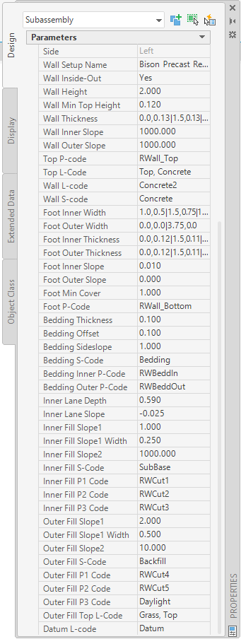
When you are finished with your design you can export the retaining wall elements to solids. That process is covered in the blog post 2/3 on Retaining Walls.1. Retaining Wall Subassembly
An example of what that means
two. Stepped profile
three. Target the retaining wall
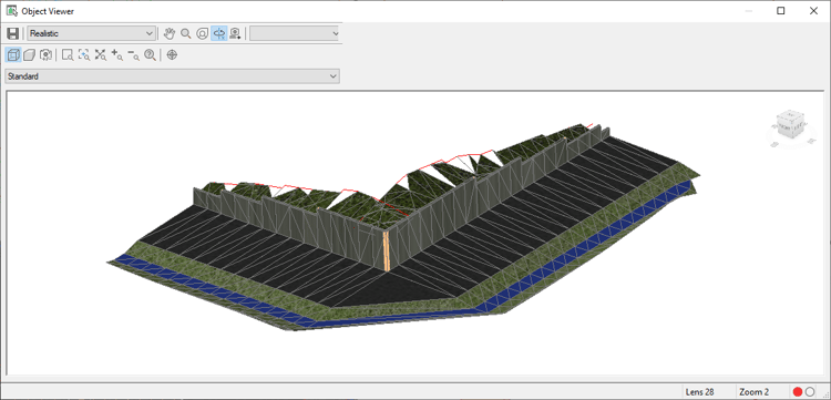
4. Extra tip: Fix the rendering problem
Want to know more than?
Source: https://blog.naviate.com/design-a-retaining-wall-with-naviate-for-civil-3d
0 Response to "how to draw a 3d retaing wall"
Enregistrer un commentaire